RPM CIRCUIT UPGRADE (Version 3 and earlier)
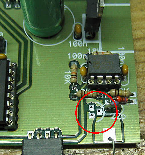
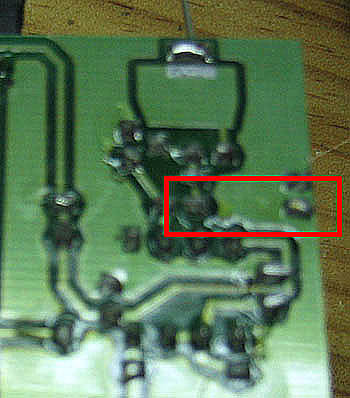
Here is shown the board without the BC547 Transistor. If has to be removed carefully because the holes are
too small. It may be needed to drill again the holes.
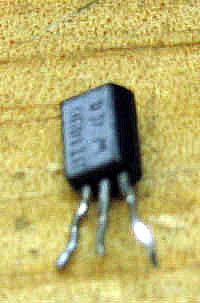
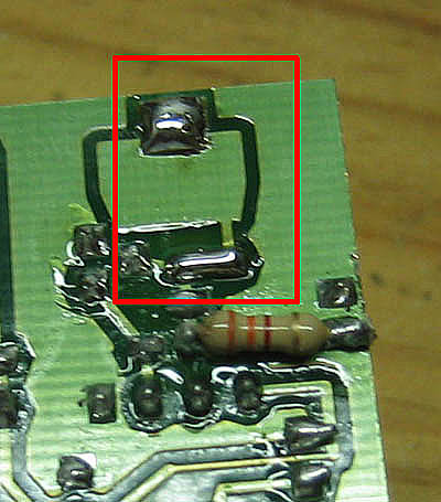
This is the BT149 SCR.
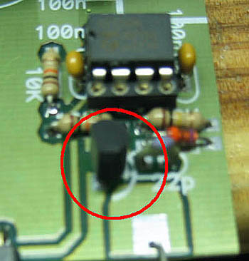
Here is shown the board with the SCR soldered.
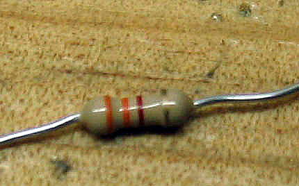
This is the 3K3 resistor.
Here is shown where goes the 3K3 resistor (in parallel with the 100K resistor).
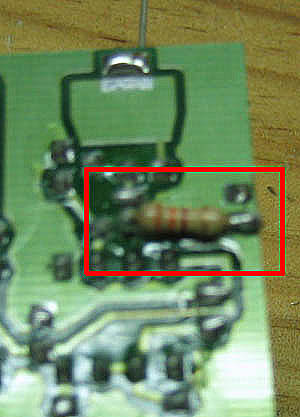
3K3 resistor soldered on the board.
2 unions have to be done soldering.
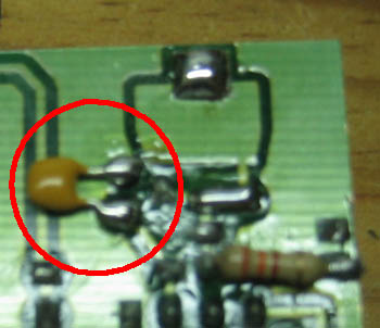
Here is shown where the 47 nf capacitor is placed (between Anode and Katode of SCR).
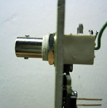
The original red connector has been replaced by a BNC connector. It has been used a plastic connector to
avoid the electrical noise to go to the display trought the aluminum plate. As the BNC connector is a bit
bigger than the red connector, the hole has to be drilled again.
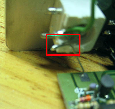
Here is shown the soldering between the signal pin on the BNC connector and the original wire from the board.
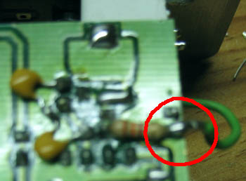
Here is shown the additional wire placed from the ground of the BNC connector and the ground of the board.
To the 3K3 resistor.
Go back
|